

Share to:
One-to-Two Power Supply
This product is widely used in industries such as pharmaceuticals, healthcare, food processing, drinking water treatment, seafood processing, tourism, entertainment, cosmetics, and poultry farming. It can also be applied for surface disinfection in venues like hotels, restaurants, cafeterias, hospitals, and livestock farms.
If you're interested in our products,Please contact us.
Product Categories
Keywords:
Details
Currently, the two main ozone-generation technologies in use are the corona discharge method and the electrolysis method.
High-voltage corona method (high-voltage discharge method): This method uses air as its raw material and maintains a certain discharge gap between two parallel high-voltage electrodes separated by a dielectric medium. When a high voltage is applied across the electrodes, the heat generated excites oxygen molecules in the air, enabling them to gain energy and collide with each other, thereby forming ozone. The corona method produces ozone using air as a feedstock; however, since air contains more than 78% nitrogen, under high-voltage conditions, nitrogen reacts with oxygen to form a new compound—nitrogen dioxide. Nitrogen dioxide is internationally recognized as a toxic substance and is one of the factors contributing to the development of cancer. Moreover, the technology used in the high-voltage corona method also limits the possibility of producing high-concentration ozone; typically, the weight-based concentration of ozone produced by this method ranges from 1% to 3%. Low-pressure electrolysis method (low-pressure water-splitting method): This method uses water as its raw material and employs solid-state noble-metal polymers as the electrolyte. By performing low-voltage electrolysis on water (H₂O), oxygen is separated to produce ozone. The resulting ozone has a weight-based concentration as high as 18% to 20%, and the accompanying gas is pure oxygen—with no harmful substances whatsoever.
The PEM electrolysis ozone generator uses pure water as its feedstock and a solid-state noble-metal polymer as the electrolyte. Employing a cation-exchange mode, it produces ozone via low-voltage electrolysis without requiring any auxiliary materials or additives. The resulting ozone concentration can reach as high as 20% (by weight, equivalent to 250–280 mg/L). The accompanying gas produced is oxygen, with no secondary pollution whatsoever. In contrast, conventional high-voltage corona discharge ozone generators use air or oxygen as feedstock and require multiple pre-treatment steps. They rely on a high-frequency, high-voltage discharge field of around 3,600 V to generate ozone, with a maximum ozone concentration typically not exceeding 10%. The byproducts of this process include nitrogen, oxygen, nitrogen oxides, and other impurities; among these, nitrogen oxides are non-degradable, toxic, and carcinogenic substances. The emergence of the third-generation ozone technology—the PEM low-voltage electrolysis ozone generation technology—has greatly expanded the application scope of ozone. This technology overcomes all the drawbacks of traditional high-voltage corona discharge methods. Its core electrode is non-consumable, resulting in lower operating costs. Moreover, the ozone concentration produced by this method is more than six times higher than that of conventional high-voltage corona discharge systems. Importantly, the ozone generated contains no harmful substances such as nitrogen oxides and causes no secondary pollution at all, making it a truly low-carbon, energy-efficient, and environmentally friendly product. Consequently, its application fields have become much broader, and it represents an inevitable trend in the development of ozone production technologies.
Third-generation ozone generation technology
Nitrogen-free compounds, no electromagnetic interference, low usage costs, and excellent safety performance.
1. Product process structure
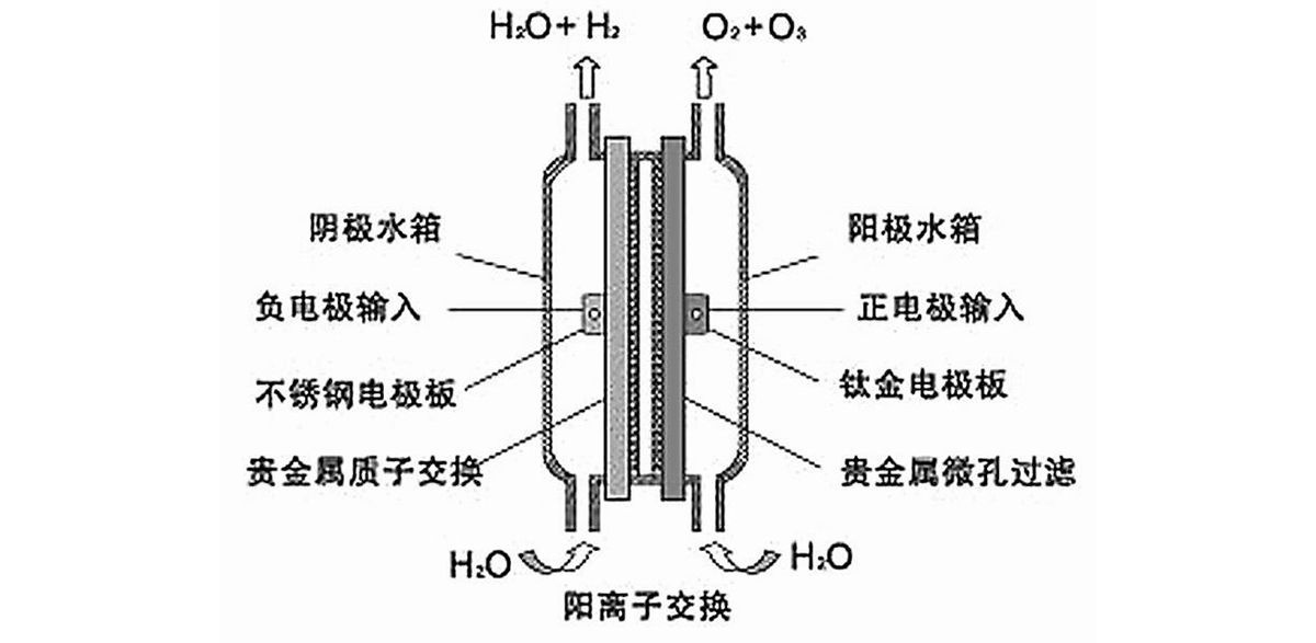
Figure 1. PEM electrode
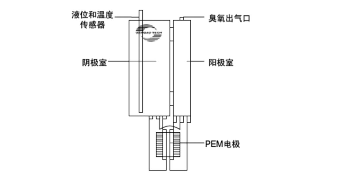
Figure 2. PEM Electrolysis Ozone Generation System
2. Precautions
2.1 PEM Electrode
The PEM electrode should be installed and activated immediately after the sealing plug is removed. The positive and negative electrodes of the product must be kept from short-circuiting; otherwise, their service life will be affected. The anode and cathode water tanks must be completely filled with deionized water (pure water or distilled water) to prevent drying, which could cause the ion-exchange membrane to fail. The electrodes must be used with a dedicated constant-current power supply. For a single electrode, the power supply should provide an output of 3–5 V / 12 A / 15–30% AC ripple. When electrodes are connected in series, the voltage requirement increases proportionally with the number of electrodes. Otherwise, the electrodes will either fail to generate ozone or be damaged by breakdown.
The electrolytic feedstock used for ozone generation in PEM electrodes is deionized water with a conductivity of ≤5 µS/cm (purified water or twice-distilled water). It is strictly prohibited to use water that does not meet these requirements as the electrolytic feedstock, as this could cause electrode short circuits, reduce the electrode's service life, or lead to failure and damage.
2.2 Installation and Connection
PEM electrodes are suitable for installation and use in ozone equipment designed to produce ozone gas or ozonated water; as long as they are properly connected to the corresponding system, they can generate high-concentration ozone.
2.2.1 Installation Requirements for PEM Electrodes in Devices Primarily Designed for Ozone Gas Generation:
Related attachments
Cathode water tank / Anode water tank / Connecting pipe / Dedicated power supply / Relay
The cathode water tank shall have a capacity of at least 1 liter and be made from non-conductive materials with excellent corrosion resistance and heat dissipation performance.
The anode water tank shall have a capacity of at least 200 ml and be made from a non-conductive material with excellent heat dissipation and strong oxidation resistance.
The connecting pipe has an inner diameter of Ø6–8 mm and must be made from a material that is tough, highly resistant to strong oxidation, and has a low coefficient of thermal deformation.
Attention: When connecting the PEM ozone generator, be sure not to reverse the anode and cathode connections. The outlet of the generator’s anode and cathode should be as vertically aligned as possible with the upper anode and cathode water tank; the shorter the distance between them, the smoother the gas output and the longer the generator’s service life and higher its efficiency.

Figure 3. Wiring Diagram of the PEM Electrolysis Ozone Generation System
1. PEM electrode 2. Hose 3. Cathode water tank 4. Anode water tank 5. Constant-current switching power supply 6. Relay
2.2.2 Installation Requirements for PEM Electrodes in Equipment Primarily Designed for Producing Ozonated Water:
Related attachments
Purified water source / Booster pump / Multi-way pipe / Connecting pipe / Mixing device / Dedicated power supply / Relay
Purified water sources should be supplied via RO reverse osmosis units or bottled purified water and distilled water.
Booster pumps should use self-priming pumps with an outlet pressure of ≥4 kg.
Multi-port water pipes should use standard water supply pipes made of stainless steel or UPVC.
The connecting pipe has an inner diameter of Ø6–8 mm and must be made from a material that is tough, highly resistant to strong oxidation, and has a low coefficient of thermal deformation.
The mixing device should adopt either a bridge-plate multi-stage turbulent mixing method or a packed porous tubular flow-through mixing method. The bridge plates or packing materials should be made of ceramic or stainless steel.
Attention: When connecting the PEM ozone generator, be sure not to reverse the positive and negative electrodes. The outlet of the generator’s positive and negative electrodes should be as vertically aligned as possible with the upper water pipe; the shorter the distance between them, the smoother the gas flow will be, and the longer the generator’s service life and the higher its efficiency will be. The ozone-water outlet should not have any resistance or valves, otherwise backflow of water could occur and damage the generator.
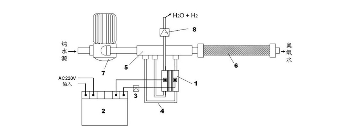
Figure 4. Connection Diagram of the PEM Electrolysis Ozone Water Generation System
Legend: (1) PEM Ozone Generator (2) Dedicated Constant-Current Switching Power Supply (3) 40A/12V DC Relay (4) Connecting Pipe (5) Multi-Port Water Pipe (6) Mixing Device (7) Booster Pump (8) Check Valve
Previous
Get a quote
Related Products


Nationwide sales hotline available 24/7
Address: Building 12, No. 168 Kechang Street, Qiubin Subdistrict, Wucheng District, Jinhua City, Zhejiang Province
E-mail:
Tel:
在线客服添加返回顶部
右侧在线客服样式 1,2,3 1
图片alt标题设置: Guangyuan Environmental
表单验证提示文本: Content cannot be empty!
循环体没有内容时: Sorry,no matching items were found.
CSS / JS 文件放置地